Four little dev boards on one breadboard: one playing the rider's legs and the drivetrain, two pretending to be bicycle sensors, and one watching the whole thing over Bluetooth. By the small hours it was printing a clean gear ladder — first through seventh and back down — off two independent radios, exactly the way the real bike will. Here's the rig, the three dead ends I walked into, and the moment it worked.
The rig
Yesterday's post ended with three rules: two clocks, feed pulses, match the product. Here is what they built.
One ESP32 plays rider and drivetrain together. A little scriptable physics engine — cadence, gear, shifts, coasting, even a slow rider surge — turns a scripted ride into two streams of pulses: one edge per crank revolution, one edge per wheel revolution.
Two identical boards. A single strap pin to ground picks the role: speed or cadence. Each does exactly what a real sensor does and nothing more — timestamp the pulses on its own pin, on its own clock, and advertise a single-function Bluetooth CSC profile.
And the head unit: an ESP32-C6 as the GearSense Central, connecting to both sensors at once and fusing them into a gear.
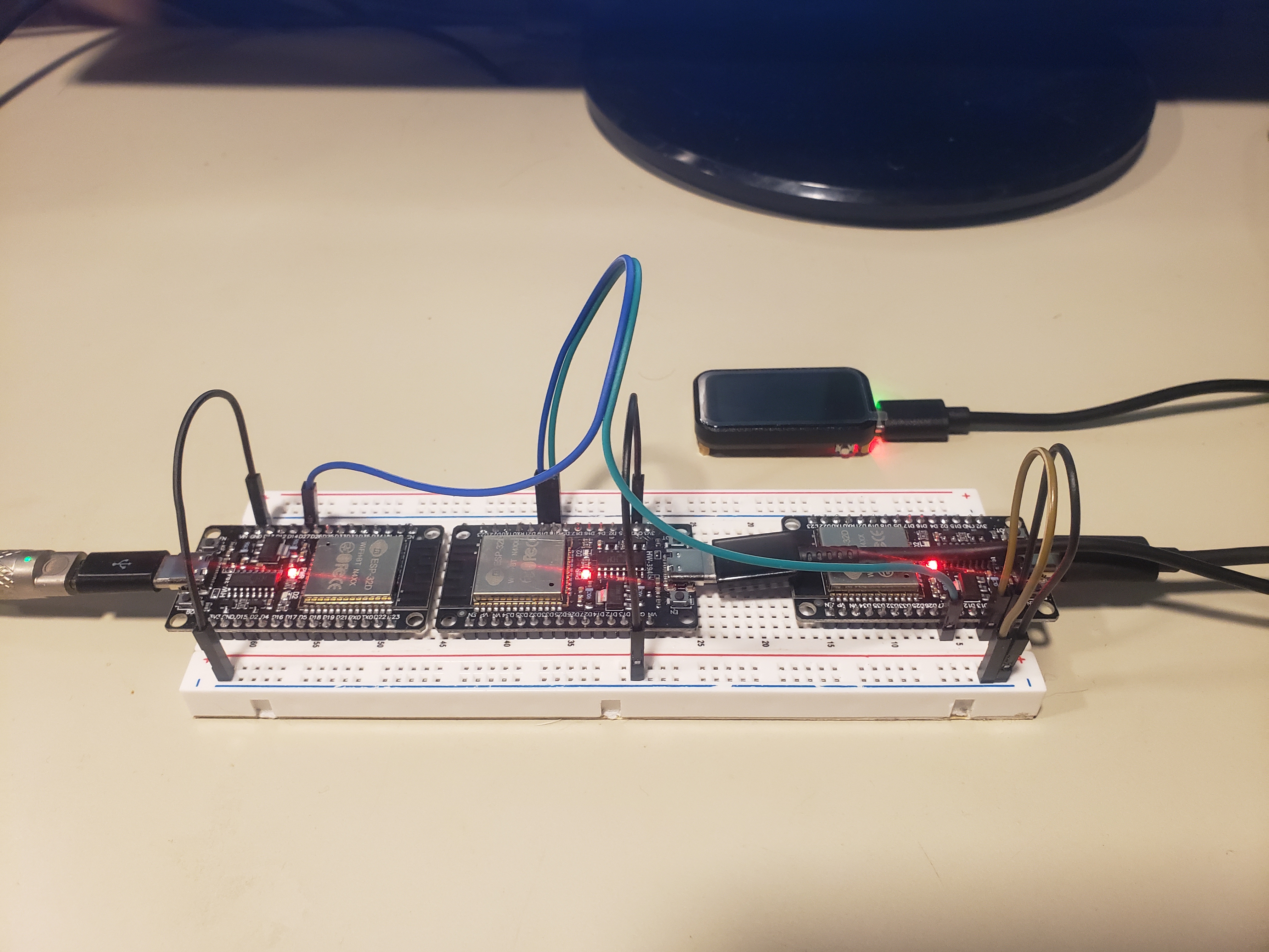
The rig: two simulator boards and the C6 head unit, all USB-powered from the same bench.
Where the chain lives
The neat part — and it took me a moment to see it — is that the two sensors are never wired to each other. They don't need to be. Real sensors aren't either; the drivetrain is what couples them. So I put the drivetrain in the only place it belongs: the generator's maths. Wheel pulses are simply crank pulses times the current gear ratio. Each wire leaving the generator is just the mechanical input one sensor happens to see — a string of edges, exactly like a magnet sweeping past a reed switch.
Bring-up, and three honest dead ends
Nothing worked the first time. In order:
-
01
The C6 said nothing Stone silence on the serial monitor. The board was running fine; I just couldn't hear it. On the ESP32-C6, Serial only reaches the USB port if "USB CDC On Boot" is enabled — otherwise it quietly goes out the UART pins, to nobody. One checkbox. (Doh.)
-
02
Stuck on "coasting" Then it ran, connected to one sensor, and sat there forever reporting a coast. I talked myself into two wrong causes — first that the sensors weren't advertising, then that my name-matching was broken — and went hunting both. The serial log was right there the whole time, telling the plain truth: the Central found the first sensor, connected, and then never discovered the second.
-
03
Scanning while connected The reason was mine. The Central stopped scanning the instant it found the first sensor so it could connect — then tried to resume scanning while holding that connection, which this radio does badly. The second sensor was never seen, the crank data never arrived, and with no cadence it sat in a permanent coast. The fix: discover both sensors first, then stop scanning for good, then connect to both.
The staircase
And then it just... worked.
# sensor 0 subscribed
# sensor 1 subscribed
wheel=2.57Hz crank=1.28Hz ratio=2.012 -> G2
wheel=2.82Hz crank=1.29Hz ratio=2.178 -> G3
wheel=3.31Hz crank=1.38Hz ratio=2.403 -> G4
wheel=3.39Hz crank=1.34Hz ratio=2.522 -> G4 (between gears)
wheel=3.69Hz crank=1.41Hz ratio=2.626 -> G5
wheel=4.10Hz crank=1.37Hz ratio=2.990 -> G6
wheel=4.94Hz crank=1.48Hz ratio=3.345 -> G7
The fused ratio walks straight up the cassette — 2.0, 2.18, 2.4, 2.67, 3.0, 3.43 — tracking the generator's climb step for step, and back down again. Two independent Bluetooth sensors, two independent clocks, fused on a third radio, and it simply knows what gear you're in.
The lines I love most are the ones that say (between gears). Every one of them lands on a shift — a ratio caught halfway between two gears, 2.52 sitting between 4th and 5th — and the classifier correctly refuses to commit, holding the last real gear until the ratio settles. That's the hysteresis earning its keep against honest, jittery, one-sample-at-a-time data.
On how this gets made
A note worth saying plainly, because theIdea.club runs in the open: the firmware across this whole stretch was written in a string of late-night sessions with Claude. I bring the bike, the instincts, and a healthy supply of bad ideas; it holds the NimBLE API and a steadier memory than mine, and it pushes back when I'm about to do something daft. I couldn't have written this code alone — and it wouldn't exist without the bike and the stubbornness either. That's the collaboration, and I'd rather be honest about it than pretend otherwise.
Loading…